PIC buttons (interrupt-based)
Previously, in PIC buttons (polling) we saw how to poll for the state of a line connect to a button, that is all fine and good but really that is not the best way to do them. The “real” way to interface with external components like that is through interrupts, a slick feature.
Interrupts provide you with lots of freedom in your code. They allow you to sit back, relax, and be told when an event occurs, and not be forced to sit and wait for it to happen.
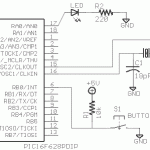
For this program, the schematic and circuit are practically the same, the only thing that changed location is the button.
Instead of looping over and over again, we simply wait, using a goto $ we are essentially goto’ing the same address over and over, “goto here, goto here, goto here…” ad nauseum. A common technique is also to use a SLEEP command, which puts the PIC in a low power mode and halts the program counter. Same effect to the user though. You of course could do ‘real’ work too instead of just burn cycles.
Once the button is pressed and released, the PIC will generate an interrupt, forcing the program to goto memory location 4. This is labeled in the code as ISR (Interrupt Service Routine).
For this program we are using the RB0/INT Interrupt. This interrupt occurs when there is a low-high change in PORTB,0. It can also be configured for high-low as well.
To enable this, we set INTCON,INTE. This bit says we want to know if a change occurs. To enable interrupts in general, we must then set INTCON,GIE. This lets all enabled interrupts occur.
We then wait for the interrupt. Once it occurs, GIE is automatically cleared so we can’t have them inside each other, and blink the LED a couple times. We then clear the interrupt flag, saying we’ve handled the interrupt (INTCON,INTF). We then re-enable interrupts and return from the interrupt: retfie.
It should be noted that if we were using more than one interrupt type, we would have needed to check the flag bits to find out which one interrupted us. We then handle it, and clear its flag. The PIC is somewhat crippled in this manner. Any and all interrupts generated and thrown into address 4 and “we” have to figure out which one occured. Many higher end MCU’s will have a table of addresses to jump to for each particular interrupt type, we then code in each location the correct routine and the processor knows which to call based on what happens.
Downloads
- Source Code (zip)
